Use Templates to Create Custom Shapes and Containers
- 9 minutes to read
The DiagramControl allows you to use shape templates to define shapes and containers in XML:
| Template | Description |
|---|---|
ShapeTemplate |
Describes a diagram shape. |
ContainerShapeTemplate |
Describes a diagram container. |
These templates can consist of the following segments:
| Segment | Description |
|---|---|
| Start | Specifies the start point of the geometry and includes customization properties. A shape can consist of multiple geometries. |
| Line | Defines a line with start and end points. |
| Arc | Defines an arc with size and direction. |
Refer to the following section for more information: Segments.
Create a Shape Template
The code sample below defines a simple shape template and displays it in the Shapes Panel:

<Shapes xmlns:xsd="http://www.w3.org/2001/XMLSchema" xmlns:xsi="http://www.w3.org/2001/XMLSchema-instance">
    <ShapeTemplate Id="MyEllipse" DefaultSize="120, 100">
        <Start X="0" Y="0.5"/>
        <Arc X="1" Y="0.5" Direction="Clockwise" Size="CreateSize(W/2,H/2)"/>
        <Arc X="0" Y="0.5" Direction="Clockwise" Size="CreateSize(W/2,H/2)"/>
    </ShapeTemplate>
</Shapes>
using (var stream = Assembly.GetExecutingAssembly().GetManifestResourceStream("WinDiagramSample.CustomShapes.xml")) {
    var stencil = DiagramStencil.Create(
        "CustomStencil",
        "Custom Shapes",
        stream,
        shapeName => shapeName
    );
    DiagramToolboxRegistrator.RegisterStencil(stencil);
}
diagramControl1.SelectedStencils = new StencilCollection() { "CustomStencil" };
Pre-configure Custom Shapes
When you create diagram shapes from XAML (XML) templates, you cannot control the initial shape size and other settings. To pre-define those attributes, create and register a FactoryItemTool. For basic information about that class, review the first example in the overview topic: Create Custom Diagram Items.
Note that you must register both the shape class and the tool within the diagram. That means you will have two separate items in the Shapes Panel. If users do not need to access the original shape item without pre-defined settings, register the shape in an invisible stencil:
void RegisterStencil() {
    // Create a visible stencil:
    var stencil = new DiagramStencil("CustomStencil", "Custom Shapes");
    FactoryItemToolForCustomShape(stencil);
    DiagramToolboxRegistrator.RegisterStencil(stencil);
    diagramControl1.SelectedStencils = new StencilCollection() { "CustomStencil" };
}

public void FactoryItemToolForCustomShape(DiagramStencil stencil) {
    DiagramControl.ItemTypeRegistrator.Register(typeof(DiagramShapeEx));
    // Create an invisible stencil that contains shapes from the CustomShapes.xml file:
    using (var stream = Assembly.GetExecutingAssembly().GetManifestResourceStream("WinDiagramSample.CustomShapes.xml")) {
        var invisibleStencil = DiagramStencil.Create(
            "InvisibleStencil",
            "Invisible Stencil",
            stream,
            shapeName => shapeName,
            // Hide this stencil from the Shapes Panel:
            false
        );
        DiagramToolboxRegistrator.RegisterStencil(invisibleStencil);
    }
    // Define a tool that obtains Shape1 form the invisible stencil and specifies its settings:
    var itemTool = new FactoryItemTool(
        "CustomShape2",
        () => "Custom Shape 2",
        diagram => new DiagramShapeEx() {
            Shape = DiagramToolboxRegistrator.GetStencil("InvisibleStencil").GetShape("MyEllipse"),
            CustomProperty = "Some value"
        },
        new System.Windows.Size(200, 200),
        false
    );
    // Add this tool to the visible stencil:
    stencil.RegisterTool(itemTool);
}
Parameters
ShapeTemplate and ContainerShapeTemplate support the following common parameters:
Id- Specifies a unique identifier for the template.
DefaultSize- Specifies a default size for the generated shape/container.
ConnectionPoints- Specified a collection of connection points assigned to the shape/container.
EditorBoundsSpecifies bounds that display the content editor.
EditorBounds="CreateRect(0,Height - HeaderHeight,Width,HeaderHeight)"Rows- Specifies rows that split the shape/container layout.
Columns- Specifies columns that split the shape/container layout.
ShapeTemplate and ContainerShapeTemplate also have parameters that specify options specific to each element.
ShapeTemplate Parameters
IsQuick- Specifies whether to display the shape in the Quick Shapes section of the Shapes Panel.
UseBackgroundAsForeground- Specifies whether to use the shape’s background color as its foreground color.
Parameters- Specifies a collection of parameters that transform shape geometry at runtime.
ContainerShapeTemplate Parameters
ActualPaddingSpecifies paddings for the container canvas.
ActualPadding="CreatePadding(Padding.Left, Padding.Top, Padding.Right, Padding.Bottom + HeaderHeight)"CollapseButtonPaddingSpecifies paddings for the collapse button.
CollapseButtonPadding="CreatePadding(0,0,10,10)"CollapseButtonLocationSpecifies the collapse button location.
CollapseButtonLocation="CreatePoint(24,0)"CollapseButtonSize- Specifies collapse button size.
Functions
Several properties (for example, Size) require that you use a function to specify this property value. The following table lists the default functions:
| Function | Description |
|---|---|
CreateSize(double width, double height) |
Returns a Size object. |
CreatePoint(double x, double y) |
Returns a Point object. |
CreatePadding(double left, double top, double right, double bottom) |
Returns a Thickness object. |
CreateRect(double top, double left, double width, double height) |
Returns a Rect object. |
Segment properties also accept keywords that refer to shape/container attributes:
W– An element width.H– An element height.P– A Parameter value. Use indexes to refer to a specific parameter (P0,P1, and so on).
You can use these keywords in expressions that calculate values:
Size="CreateSize(W/2, H/2)"

X="Cos(P0*3.14/2)"
ShapeTemplates accept functions that implement the ICustomFunctionOperator interface. The Criteria Language Syntax allows you to calculate shape parameters. You can register and use custom functions as described in the following help topic: Custom Function Criteria Operators.
Segments
Each segment has X and Y properties that define its coordinates within the element border. These properties use relative coordinates (from “0” to “1” relative to element height and width). X="0" Y="0" corresponds to the top-left element corner, X="1" Y="1" corresponds to the bottom-right corner.
Segments are drawn from the point defined by their X and Y values to the preceding segment’s X and Y values. The Arc segment has the additional Size parameter.
The X, Y, and Size properties support Criteria Language Syntax.
<Line X="Cos(P0*3.14/2)" Y="Sin(P0*3.14/2)"/>
Start Segment
The Start segment specifies the start point for the geometry and describes geometry appearance. A template can contain several Start segments.
The Start segment has the following appearance options:
| Property | Description |
|---|---|
| FillBrightness | Specifies the brightness level of the color used to fill in the geometry. |
| FillColor | Specifies the color used to fill in the geometry. |
| IsSmoothJoin | Specifies whether to round geometry corners. |
| StrokeColor | Specifies the color that paints the geometry outline. |
| StrokeThickness | Specifies the thickness of the geometry outline. |
| StrokeDashArray | Specifies the dash pattern that draws the outline. |
<Start X="0" Y="0" FillColor="Brown" StrokeThickness="2" StrokeColor="Red"/>
You can use the IsNewShape property to specify whether the Start segment initializes a new independent part of the geometry.
Line Segment
The Line segment specifies a point and draws a line from this point to the Start segment or the previous segment’s end point.
<Line X="1" Y="1"/>
This segment does not contain properties to control its appearance.
Arc Segment
The Arc segment draws an arc from the point specified by X and Y properties to the end point of the previous segment or the Start segment.
This segment contains the Direction property that specifies the arc direction (Clockwise or Counterclockwise).
<Arc X="1" Y="0" Size="CreateSize(W/2, H/2)" Direction="Counterclockwise"/>
This segment does not contain properties to control its appearance.
Connection Points
ShapeTemplate and ContainerShapeTemplate include the ConnectionPoints property that allows you to specify connection points. This property accepts ShapePoint objects that describe X and Y coordinates. These properties use relative coordinates (from “0” to “1” relative to element height and width). To use absolute coordinates, set the Kind property to Absolute.
<ShapeTemplate.ConnectionPoints>
    <ShapePoint X="0" Y="0"/>
    <ShapePoint X="1" Y="0"/>
    <ShapePoint X="0" Y="1"/>
</ShapeTemplate.ConnectionPoints>
Shape Transformations
ShapeTemplates allow you to define interactive points that transform shape geometry. Follow the steps below to add an interactive point:
- Add a Parameter object to the
ShapeTemplate.Parameterscollection. - Specify its default, min, and max values (DefaultValue, Min, and Max properties).
Define a function that describes a point position (a yellow handle) in the shape. Assign this function to the Point property.
You can use the
Pvariable to pass Parameter.Value to function parameters.Specify a function that transforms the point position into shape-relative coordinates. Assign this function to the Value property.
You can use the
P.XandP.Yvariables (that correspond to the point’sXandYcoordinates) to pass Parameter.Point to the Parameter.Value property.
Note
Each parameter can return only a single double value. As a result, each point can be used to change values along only one path.
The code snippet below uses a parameter to allow users to transform the shape (change size of the Arc segment):
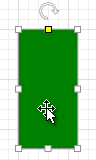
<ShapeTemplate Id="CustomizableArc" DefaultSize="60, 120">
    <Start X="0" Y="0" FillColor="Green"/>
    <Arc X="1" Y="0" Size="CreateSize(W/2, P0 * H)" Direction="Counterclockwise"/>
    <Line X="1" Y="1"/>
    <Line X="0" Y="1"/>
    <Line X="0" Y="0"/>
    <ShapeTemplate.Parameters>
        <Parameter DefaultValue="0"
                   Point="CreatePoint(W / 2, P * H)"
                   Value="P.Y / H"
                   Min="0" Max="1"/>
    </ShapeTemplate.Parameters>
</ShapeTemplate>
The Point and Value properties accept any function that implements the ICustomFunctionOperator interface and returns the corresponding value type.
Rows and Columns
ShapeTemplate.Rows and ShapeTemplate.Columns properties (ContainerShapeTemplate.Rows and ContainerShapeTemplate.Columns) allow you to define a grid-based layout and arrange complex shape elements. Elements are automatically aligned in rows and columns.
Rows and Columns properties accept absolute values, H and W keywords, and expressions. You can use these keywords to define rows and columns with relative values.
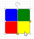
The following code snippet defines a shape that consists of four rectangles arranged in two columns and two rows:
<ShapeTemplate
    Id="Frame"
    DefaultSize="200,200"
    Rows="H*0.5;H*0.5" Columns="W*0.5;W*0.5"
    Style="ShapeId.Moderate5">
    <Start X="0" Y="0" FillColor="Blue"/>
    <Line X="1" Y="0"/>
    <Line X="1" Y="1"/>
    <Line X="0" Y="1"/>
    <Start X="0" Y="1" FillColor="Red"/>
    <Line X="1" Y="1"/>
    <Line X="1" Y="2"/>
    <Line X="0" Y="2"/>
    <Start X="1" Y="0" FillColor="Green"/>
    <Line X="2" Y="0"/>
    <Line X="2" Y="1"/>
    <Line X="1" Y="2"/>
    <Start X="1" Y="1" FillColor="Yellow"/>
    <Line X="2" Y="1"/>
    <Line X="2" Y="2"/>
    <Line X="1" Y="2"/>
</ShapeTemplate>
Rows and Columns properties accept Parameter values. You can use the ShapeTemplate.Parameters property to create shapes with interactive row and column definitions:
Rows="H*P0;H*(1-P0)" Columns="W*P1;W*(1-P1)"

<ShapeTemplate.Parameters>
    <Parameter DefaultValue="0.5"
               Point="CreatePoint(W, P * H)"
               Value="P.Y / H"
               Min="0" Max="1"/>
    <Parameter DefaultValue="0.5"
               Point="CreatePoint(P * W, H)"
               Value="P.X / W"
               Min="0" Max="1"/>
</ShapeTemplate.Parameters>