Annotations Position and Layout
- 2 minutes to read
This document describes how you can position annotations.
Relative and Absolute Position
The position of an annotation is specified via its Annotation.ShapePosition property, and it can be of two types.
Position Type | Description |
|---|---|
Free Position
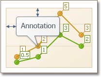
| If the Annotation.ShapePosition property is set to the FreePosition type, you can specify whether the anchor point is targeted to the chart or a pane (FreePosition.DockTarget), and choose the corner where the annotation is docked (FreePosition.DockCorner). In addition, you can specify the indents from the annotation and its dock target element (chart or pane), via the FreePosition.InnerIndents and FreePosition.OuterIndents properties, whose values are summarized. |
Relative Position
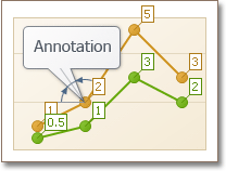
| If the Annotation.ShapePosition property is set to the RelativePosition type, you can specify the annotation’s angle at its anchor point (RelativePosition.Angle), and the length of its connecting line (RelativePosition.ConnectorLength). |
Annotation Layout
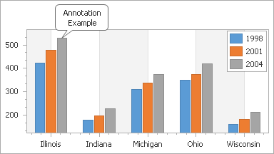
By default, annotations that reside within the diagram and do not fit in its dimensions are cut off. You can make an annotation behave similarly to series labels, so that it shrinks the diagram, to completely fit, via the Annotation.LabelMode property.
| LabelMode = false | LabelMode = true |
|---|---|
 |
 |
To learn about the limitations imposed by using the label mode, refer to the Annotation.LabelMode property’s description.
In addition, you can customize the size of the annotation (ImageAnnotation.SizeMode and TextAnnotation.AutoSize), and the angle by which the annotation’s shape (where the annotation’s image or text is displayed) is rotated (Annotation.Angle).
When multiple annotations are displayed, you can control their Z-order, via the Annotation.ZOrder property.