Creating Shapes and Containers Using Shape Templates
- 5 minutes to read
This document describes how to define shapes in XML using shape templates. The ShapeTemplate is the main element that contains shape description. The ContainerShapeTemplate is used to describe containers.
Segments
You can define the shape geometry using the following segments :
- Start - Specifies the start point of the geometry and provides customization properties. A shape can consist of multiple geometries.
- Line - Defines a line.
- Arc - Defines an arc with the size and the direction.
Each segment provides the X and Y properties that define its relative coordinates within the shape border. X=”0” Y=”0” corresponds to the top-left corner of the shape border, X=”1” Y=”1” corresponds to the bottom-right corner. The Line and Arc segments are drawn from the point defined by the preceding segment’s X and Y values to the point defined by their X and Y.
The arc segment’s size is specified using the CreateSize method that accepts absolute width and height values as parameters. You can pass the shape’s current width and height as the method’s parameters using the W and H variables respectively. To create an arc with a fixed height or width, pass a static value instead of a variable. The code snippet below illustrates how to create an arc half the size of the shape.
<Arc X="1" Y="0" Size="CreateSize(W/2, H/2)" Direction="Counterclockwise" />
Consecutively defined geometries can be merged to form a single shape. To do this, set the Start.IsNewShape property to false for the second and subsequent geometries.
The Start class provides properties that define the appearance of the geometry:
- Start.FillBrightness sets the brightness level of the color used to fill in the geometry.
- Start.FillColor sets the color used to fill in the geometry.
- Start.IsSmoothJoin sets whether to round the corners of the geometry.
- Start.StrokeColor sets the color used to paint the outline of the geometry.
- Start.StrokeThickness sets the thickness of the geometry’s outline.
The X, Y and Size properties support Criteria Language Syntax. The example below illustrates the cosine and sine functions.
<ShapeTemplate x:Key="{ShapeKey Shape3}" DefaultSize="60, 120">
    <Start X="0" Y="0"/>
    <Line X="Cos(P0*3.14/2)" Y="Sin(P0*3.14/2)"/>
    <Line X="0.5" Y="1"/>
    <Parameters>
        <Parameter DefaultValue="0.1"
                Point="CreatePoint(W / 2, P * H)"
                Value="P.Y / H"
                Min="0" Max="1" />
    </Parameters>
</ShapeTemplate>
Connection Points
The ShapeTemplate.ConnectionPoints property allows you to specify the connection points the ShapePoint class instances represent. See the code snippet below.
<ConnectionPoints>
    <ShapePoint X="0" Y="0" />
    <ShapePoint X="1" Y="0" />
    <ShapePoint X="0" Y="1" />
    <ShapePoint X="1" Y="1" />
</ConnectionPoints>
Shape Transformations
You can specify shape parameters by adding the Parameter class instances to the ShapeTemplate.Parameters collection. End-users can transform the shape by dragging the yellow handles that visually represent parameters. Each parameter is characterized by its Parameter.Value property. The Parameter.Point property specifies the handle’s coordinates using the CreatePoint method. Use the P variable to pass the current Parameter.Value to this method’s parameters.
Point="CreatePoint(W / 2, P * H)"
To pass the current Parameter.Point to the Parameter.Value definition, use the P.X and P.Y variables that correspond to the point’s X and Y coordinates.
Value="P.Y / H"
The code snippet below illustrates how to define a parameter that changes its value from 0 to 1 depending on its current Y coordinate. An end-user cannot change the X coordinate.
<Parameter DefaultValue="0"
                       Point="CreatePoint(W / 2, P * H)"
                       Value="P.Y / H"
                       Min="0" Max="1" />
You can pass the parameter’s value to the CreateSize method. The P0 variable corresponds to the first parameter within the ShapeTemplate.Parameters collection, the P1 corresponds to the second parameter and so on. The code snippet below illustrates how to use this parameter to allow an end-user to transform the shape by changing the Arc segment’s size.
<ShapeTemplate x:Key="{ShapeKey CustomizableArc}" DefaultSize="60, 120">
        <Start X="0" Y="0" FillColor="Green"/>
        <Arc X="1" Y="0" Size="CreateSize(W/2, P0 * H)" Direction="Counterclockwise" />
        <Line X="1" Y="1"/>
        <Line X="0" Y="1"/>
        <Line X="0" Y="0"/>
        <Parameters>
            <Parameter DefaultValue="0"
                       Point="CreatePoint(W / 2, P * H)"
                       Value="P.Y / H"
                       Min="0" Max="1" />
        </Parameters>
</ShapeTemplate>
The following image shows the result:

Rows and Columns
The ShapeTemplate.Rows and ShapeTemplate.Columns properties allow you to define a grid-based layout and arrange complex shape elements. Elements are automatically aligned in rows and columns.
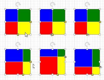
The following code snippet illustrates how to define a shape that consists of four rectangles arranged in two columns and two rows. An end-user can customize row and column sizes.
<ShapeTemplate x:Key="{ShapeKey FourRectangles}" DefaultSize="100, 100" Rows="H*P0;H*(1-P0)" Columns="W*P1;W*(1-P1)">
        <Start X="0" Y="0" FillColor="Blue"/>
        <Line X="1" Y="0"/>
        <Line X="1" Y="1"/>
        <Line X="0" Y="1"/>
        <Start X="0" Y="1" FillColor="Red"/>
        <Line X="1" Y="1"/>
        <Line X="1" Y="2"/>
        <Line X="0" Y="2"/>
        <Start X="1" Y="0" FillColor="Green"/>
        <Line X="2" Y="0"/>
        <Line X="2" Y="1"/>
        <Line X="1" Y="2"/>
        <Start X="1" Y="1" FillColor="Yellow"/>
        <Line X="2" Y="1"/>
        <Line X="2" Y="2"/>
        <Line X="1" Y="2"/>
        <ConnectionPoints>
            <ShapePoint X="0.5" Y="0" />
            <ShapePoint X="1" Y="1" />
            <ShapePoint X="0.5" Y="2" />
            <ShapePoint X="0" Y="1" />
        </ConnectionPoints>
        <Parameters>
            <Parameter DefaultValue="0.5"
                       Point="CreatePoint(W, P * H)"
                       Value="P.Y / H"
                       Min="0" Max="1" />
            <Parameter DefaultValue="0.5"
                       Point="CreatePoint(P * W, H)"
                       Value="P.X / W"
                       Min="0" Max="1" />
        </Parameters>
</ShapeTemplate>
The image below shows the result.

See the examples: