How To: Create a Linear Gauge (Design-time)
- 3 minutes to read
This is the second tutorial of the XtraGauges Getting Started series. It will guide you through the process of creating a Linear Gauge and adjusting its common settings.
This tutorial consists of the following steps.
- Create a New Project and Add a Gauge Control
- Run the Preset Manager
- Load the Required Gauge Preset
- Customize Gauge Scales
- Result
Step 1. Create a New Project and Add a Gauge Control
In this step, we will perform the common actions required when you add a Gauge control to your application.
- Create a new Windows Forms Application project (Visual Studio 2012, 2013, 2015, 2017 or 2019) or open an existing one.
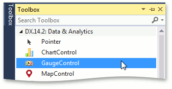
Add the GaugeControl component to your project. To do this, locate the GaugeControl item in the Visual Studio toolbox on the DX.19.2: Data & Analytics tab and drop it onto the form.
Step 2. Run the Preset Manager
Locate the Gauge’s smart tag and click Run Preset Manager.
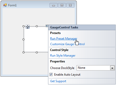
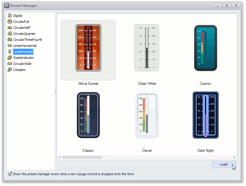
After that, you will see the following wizard.
Note that after you drop the Gauge in the previous step, the Gauge Preset Manager may be invoked automatically (if its “Show the preset manager every time a new Gauge control is dropped onto the form” option is enabled).
The Preset Manager allows you to create a ready-to-use gauge by loading it from the preset collection. The next step demonstrates how it is done.
Step 3. Load the Required Gauge Preset
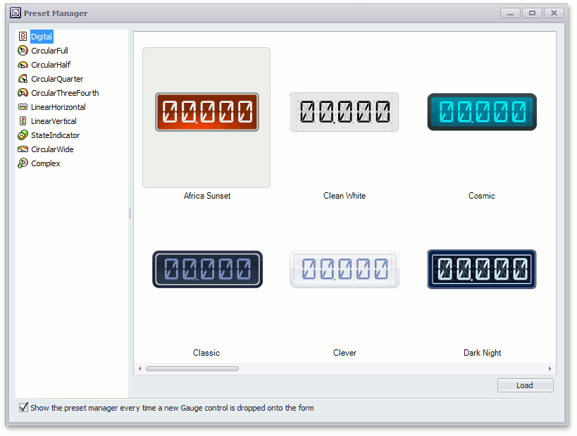
- In the Preset Manager, click LinearVertical to display presets with vertical linear gauges.
You can load the gauge preset in one of two ways:
- double-click the required preset on the Preset Manager;
- select a preset and click the Load button at the bottom of the Preset Manager.
The following image shows how to load the Africa Sunset preset using the second approach.
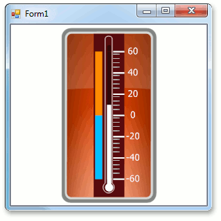
After that, the Form1 window should look like the following.
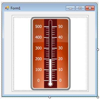
As you can see, the new Gauge contains a lever bar, two scales, and background layer.
Step 4. Customize Gauge Scales
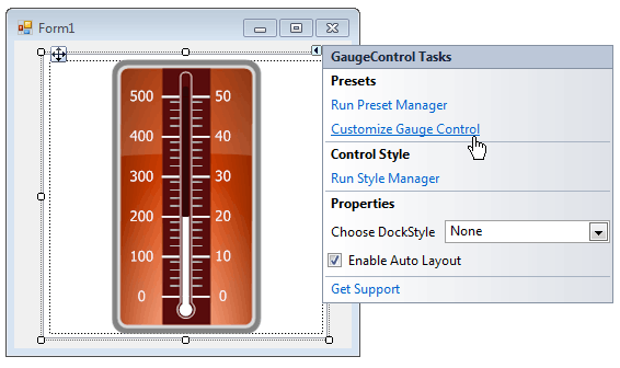
- To access the gauge’s elements and customize their settings, run the Visual Gauge Control Designer.
To do this, locate the Gauge’s smart tag and in the invoked menu, click Customize Gauge Control, as shown below.
Let’s delete the second scale of the linear gauge.
To accomplish this, select scale2 in the Visual Gauge Control Designer, and remove it using the Remove button.
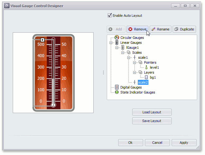
On the Designer left side, you can see the linear gauge containing only the first scale (see the image below).
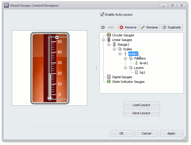
- To customize a scale, double click scale1 node, as shown above.
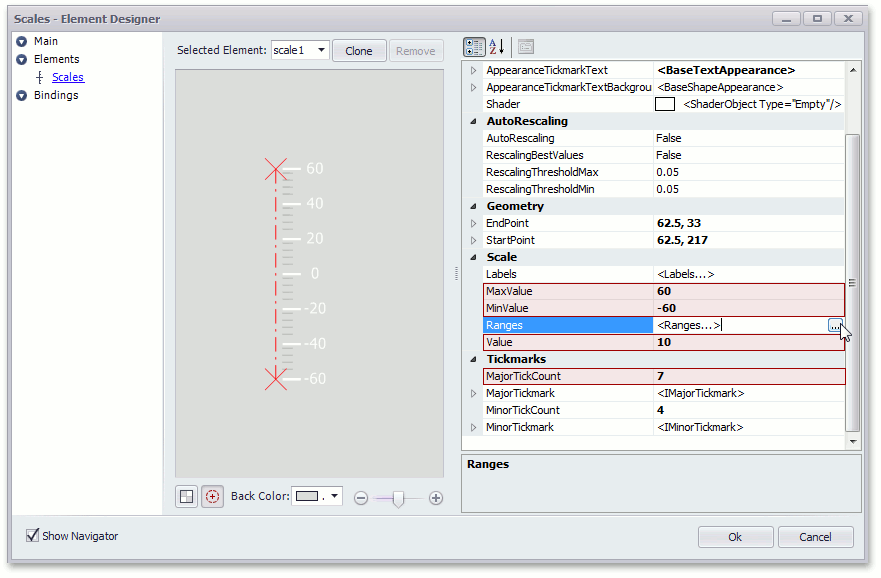
In the invoked Scales-Element Designer, change the scale’s properties and click the Ranges… button as shown in the following image.
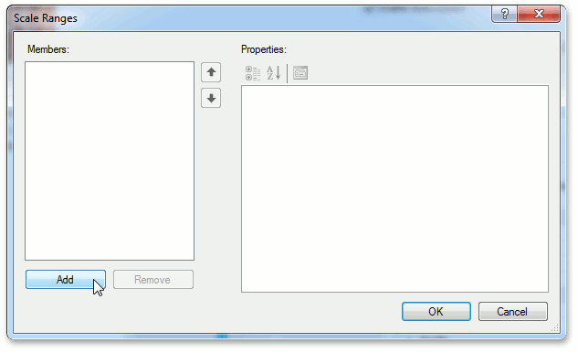
In the Ranges editor, add two range elements to the circular gauge by clicking the Add button.
Specify the Range0 properties as shown below.
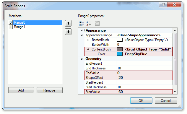
For the Range1, execute the following changes and click OK.
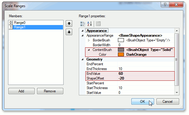
- Click OK to close the Scale Ranges editor.
- Click OK to close Scales -Element Designer.
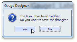
Then, you will see the following confirmation window.
Note
The confirmation window occurs in the Gauge Designer every time the current layout is changed.
- Click Yes to confirm the operation, as shown above.
- Click OK to close the Visual Gauge Control Designer.
Step 5. Result
Run the application to see the result.