How to: Create a Circular Gauge (Design-time)
- 3 minutes to read
This is the first tutorial of the XtraGauges Getting Started series. It will guide you through the process of creating a Circular gauge and adjusting its common settings.
This tutorial consists of the following steps.
- Create a New Project and Add a Gauge Control
- Run the Preset Manager
- Load the Required Gauge Preset
- Customize Gauge Scales
- Result
Step 1. Create a New Project and Add a Gauge Control
In this step, we will perform the common actions required when you add a Gauge control to your application.
- Create a new Windows Forms Application project (Visual Studio 2012, 2013, 2015 or 2017) or open an existing one.
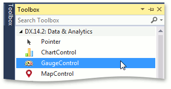
Add the GaugeControl component to your project. To do this, locate the GaugeControl item in the Visual Studio toolbox on the DX.18.2: Data & Analytics tab and drop it onto the form.
Step 2. Run the Preset Manager
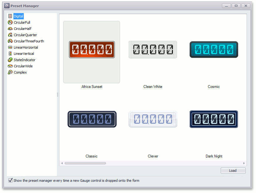
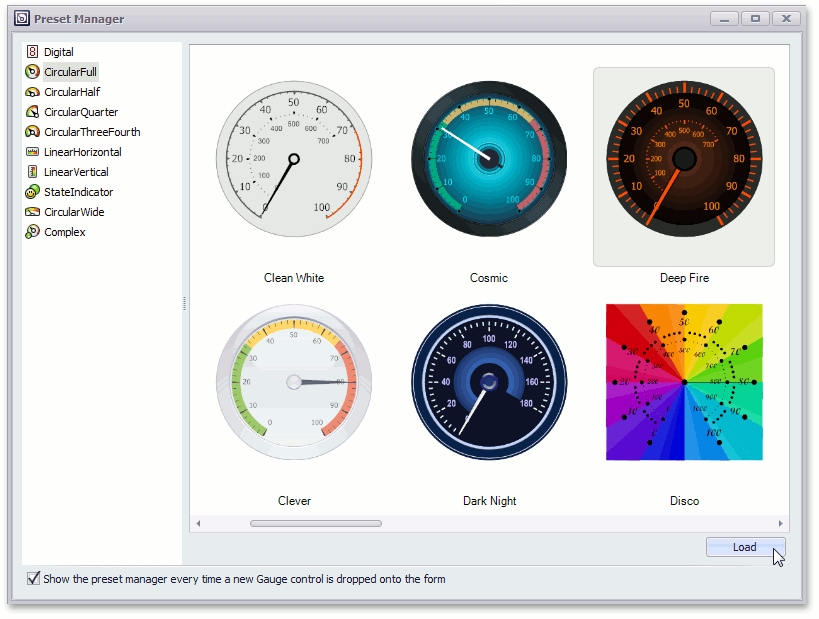
The Preset Manager allows you to apply built-in presets to your existing gauges or create a new gauge from the selected preset.
Locate the Gauge’s smart tag and click Run Preset Manager.
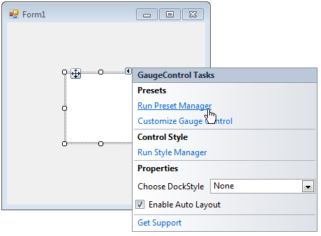
After that, you will see the following wizard.
Note that after you drop the Gauge in the previous step, the Gauge Preset Manager may be invoked automatically (if its “Show the preset manager every time a new Gauge control is dropped onto the form” option is enabled).
Step 3. Load the Required Gauge Preset
In the Preset Manager, click CircularFull to display presets with circular gauges.
You can load the gauge preset in one of two ways:
- double-click the required preset on the Preset Manager;
- select a preset and click the Load button at the bottom of the Preset Manager.
The following image shows how to load the Deep Fire preset using the second approach.
The Form1 window should look like the following.
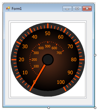
The new gauge contains two scales, a needle, spindle cap and background layer.
Step 4. Customize Gauge Scales
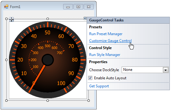
- To access the gauge’s elements and customize their settings, run the Visual Gauge Control Designer.
For this, locate the Gauge’s smart tag and in the invoked menu, click Customize Gauge Control, as shown below.
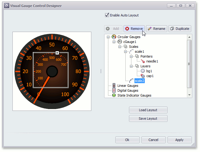
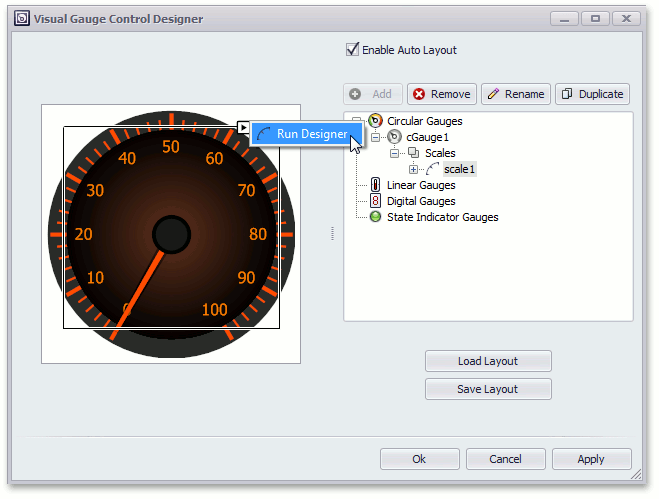
Let’s delete the inner scale. For this, select the second scale in the Gauge Designer, by clicking the scale2 node, and remove it using the Remove button.
To customize the scale settings, double-click the scale gauge element on the right side list of the Visual Gauge Control Designer or click the scale’s smart tag and select Run Designer as shown below.
Change the Scale’s properties in Scales - Element Designer and click the Ranges… button as shown below.
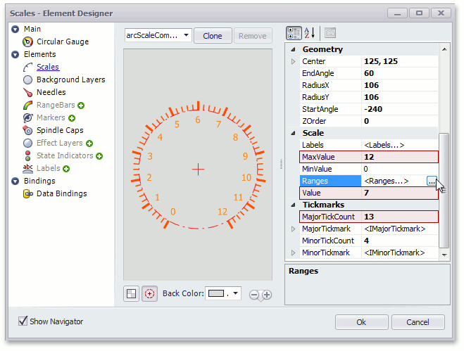
This runs the Ranges editor.
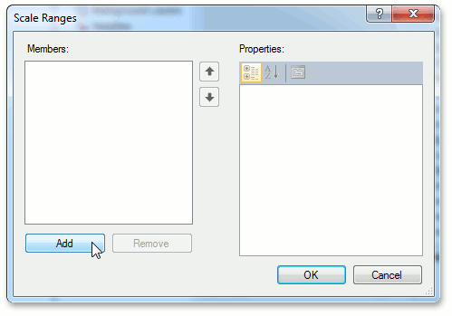
Let’s add a range to the gauge scale to show the working range of the needle element. For this, click the Add button in the Scale Ranges editor.
For a Range element, customize its color and set the BaseRange.EndValue property to 12 and BaseRange.ShapeOffset to -50, then click OK as shown below.
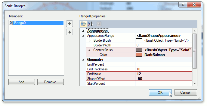
- Click OK to close the Scale Ranges editor.
- Click OK to close Scales - Element Designer.
Then, you will see the following confirmation window.
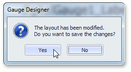
Note
The confirmation window occurs in the Gauge Designer every time the current layout is changed.
- Click Yes to confirm operation, as shown above.
- Click OK to close the Visual Gauge Control Designer.
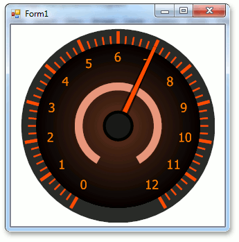
Step 5. Result
Run the application to see the result.