Coordinate System
- 3 minutes to read
This document explains how gauges are measured within a Gauge Control, the meaning of a gauge’s Z Order, and how to specify angles of gauge-specific elements.
Measuring Along the X and Y Axes
A Gauge Control can display multiple gauges of different types at the same time. Each gauge is drawn within a specific painting area - a cell, which has its own relative coordinate system. In most cases, the origin of the coordinate system is the top-left corner of the cell, with the X axis pointing to the right and the Y axis pointing down.
Painting cells have real bounds within the gauge control. However, a gauge’s size and coordinates within a cell are relative.
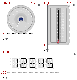
The coordinate system within each cell is relative. The origin of the coordinate system is the point with the coordinates of (0,0), which is in most cases positioned at the top-left corner of the cell. For most gauge types, a cell’s relative width and height are fixed, and these values are dependent upon the gauge type. Note that these values do not depend upon the actual bounds of the cell.
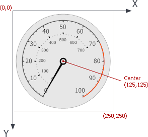
For circular gauges, a cell has a relative width and height equal to 250:
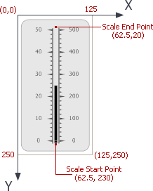
For linear gauges, a cell’s dimension along the X axis is 125, and the dimension along the Y axis is 250:
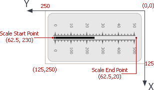
Note that for linear gauges oriented horizontally, the coordinate system is rotated 90 degrees clockwise. The top-right corner has an x,y coordinate of (0,0). The X axis points down and the Y axis points to the left.
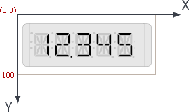
For digital gauges, a cell’s relative height is equal to 100, and the width is calculated automatically to keep its proportions:
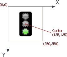
For state indicator gauges, the coordinate system is like the one for circular gauges. A cell has a relative width and height equal to 250:
Z Order
Although a gauge is two-dimensional, it is composed of overlapping layers that display various gauge elements (for example, the background layer, one or more scales, and needles). All of these layers are positioned above each other and their positions along the Z axis are determined by the Z Order.
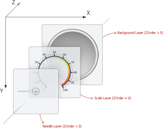
Layers with higher Z Orders are positioned below layers with lower Z Orders. For instance, needles within circular gauges have negative Z Orders, and so they are displayed above all other layers.
Measuring Angles
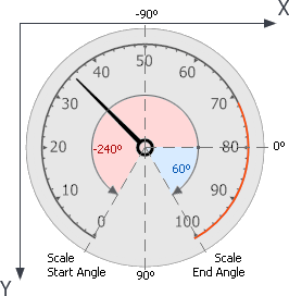
Circular gauges allow you to customize angles of specific elements (for instance, the start and end angles of a scale). Angles are measured in degrees, starting clockwise from the X axis. The following image shows how angles are specified in circular gauges:
For more information on circular gauge elements, see the following help topic: Circular Gauge (Visual Elements).